


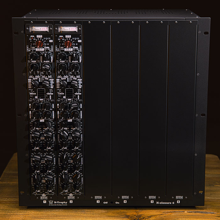
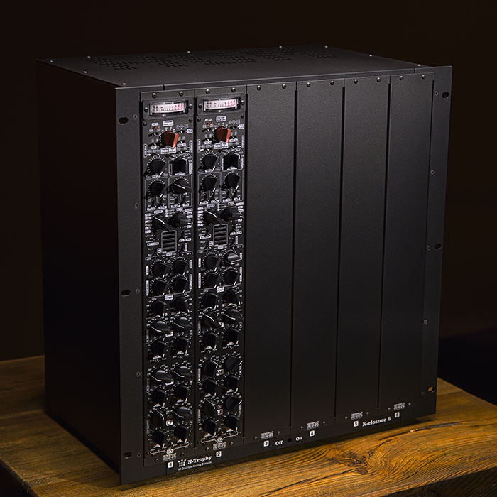
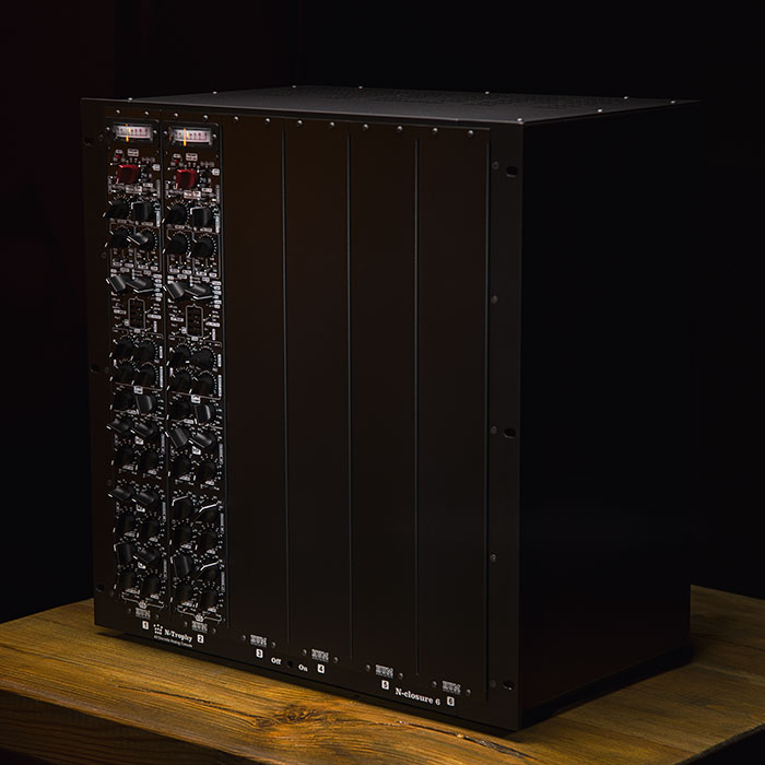
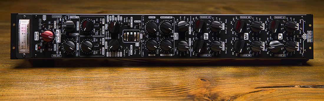
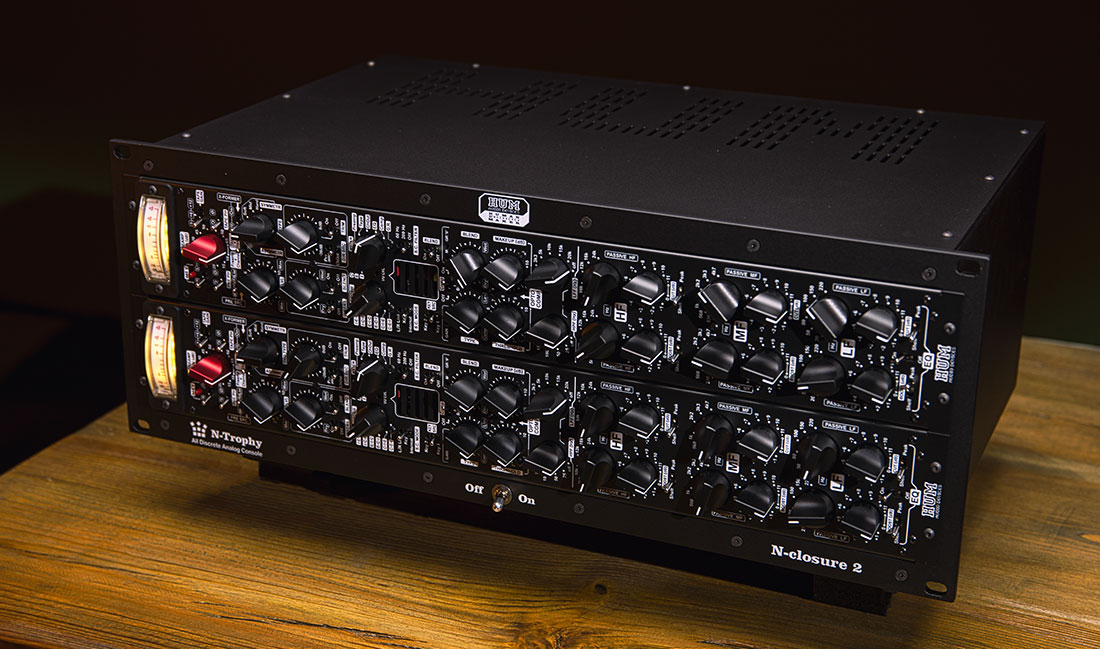
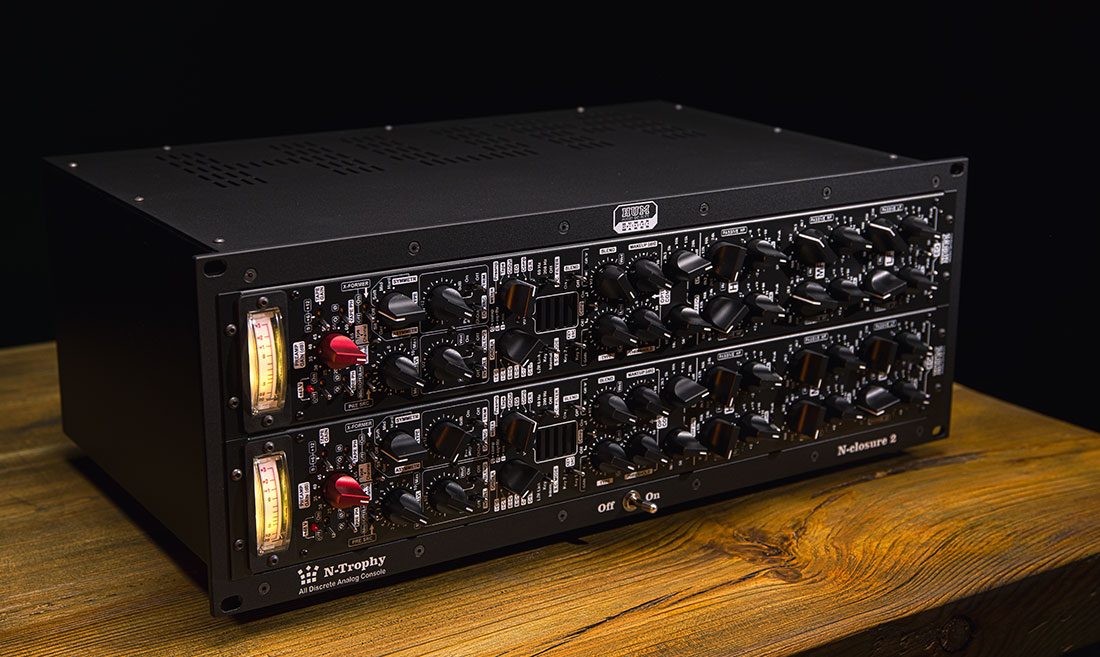
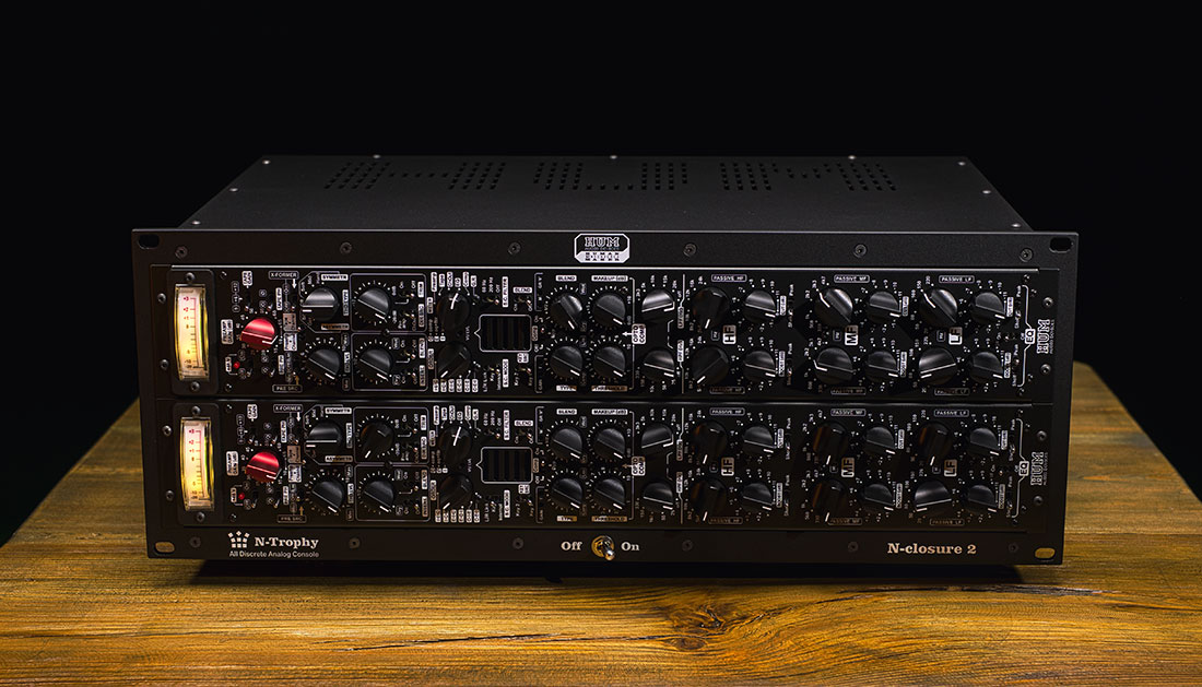
Top quality VU Meters with excellent ballistics.
PREAMP GAIN (db): Gain switch for the selected signal input.
+48 V: Phantom power switch for condenser mics.
TAPE GAIN: 0/+6/+12dB switch for TAPE IN input signal.
PRE SRC: Input source for the preamp꞉ Mic/Off/Line.
PRE PH / TAPE PH: Phase reverse switches for Mic/Line/Instr inputs and TAPE IN (line level) signals.
Preamp + Channel / Tape + Channel: Select channel’s physical input.
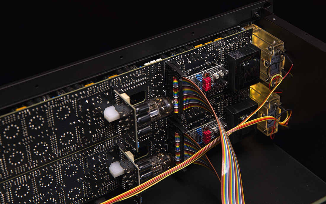
X-FORMER: Switch for the interstage audio transformer located after the mic preamp.
THD LVL / THD TYPE: Select type and level of saturation.
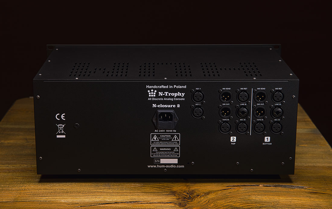
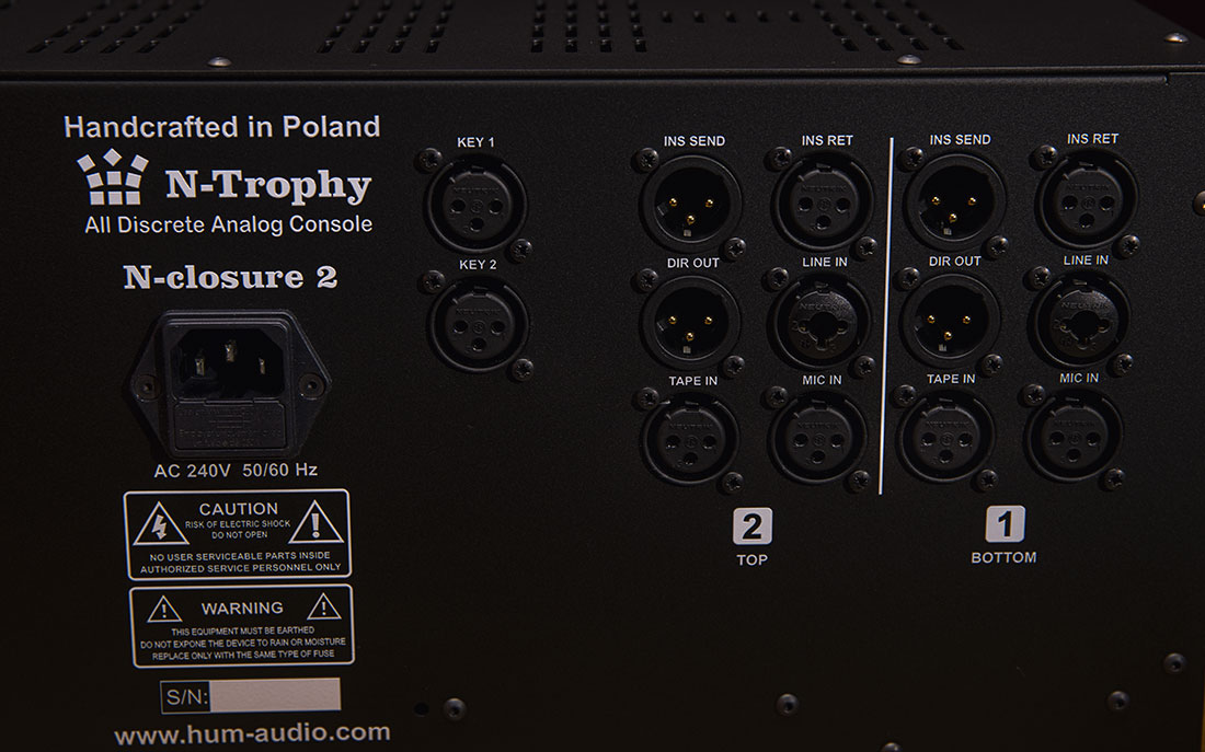
DIR SRC: Select the audio output point for DIR OUT꞉
– Preamp ‑ after the preamp, before processing
– ChOut ‑ after all sound processing in the channel
TRIM: Pot for additional trim level of DIR OUT (direct output) signal, with on/off switch.
INSERT / BLEND: Insert switch and insert dry/wet blend pot with switch. When the BLEND switch is set to off, the channel insert point signal is 100% wet.
ORDER: Select processig order꞉C (Compressor), E (EQ + filters), I (Insert).
METER: Select the metering point for the VU Meter. G.R. ‑ Gain Reduction of the Compressor.
S.C. MODE: Compressor sidechain mode꞉ Internal, L/R Link (stereo link), Key for external key inputs.
KEY SRC: Select KEY1 of KEY2 for sidechain inputs
S.C. FILTER: The cutoff frequency for detection circuit in Internal sidechain mode.
Comp: Switch in OPTO COMPRESSOR. In Byp mode the compressor is bypassed, but the tube is still active.
TYPE: Select compressor characteristics, from Comp (slow) to Lim (fast).
THRESHOLD: Compression depth. Attack and release depends on the gain reduction depth.
BLEND: dry/wet mix balance of compressed and uncompressed signal.
MAKEUP (db): Gain Makeup ‑ signal level boost after compression. Tube circuit.
LPF (Hz): Low pass filter, frequency selection with stepped rotary switch. 6dB/oct slope.
HPF (Hz): High pass filter, frequency selection with stepped rotary switch. 6dB/oct slope.
HF: High‑frequency passive EQ, independently selectable frequencies for BOOST and CUT. Equipped with stepped rotary switches. Gently overlapping (6dB/oct).
BOOST (dB): Amount of boost (dB) for HF band.
CUT (dB): Amount of cut (dB) for HF band.
Shelf/Peak switches for BOOST an CUT.
MF: Mid‑frequency passive EQ, independently selectable frequencies for BOOST and CUT.
Equipped with stepped rotary switches. Gently overlapping (6dB/oct).
Amount of boost (dB) for MF band.
Amount of cut (dB) for MF band.
LF: Low‑frequency passive EQ, independently selectable frequencies for BOOST and CUT.
Equipped with stepped rotary switches. Gently overlapping (6dB/oct).
Amount of boost (dB) for HF band.
Amount of cut (dB) for HF band.
Shelf/Peak switches for BOOST an CUT.
EQ: On/Off switch for the channel EQ circuits.


